Microwave Journal – Gapwaveguide Technology: A Game Changer for Automotive Radars
This article was published in the Microwave Journal.
Carlo Bencivenni, Abolfazl Haddadi, Abbas Vosoogh and Marcus Hasselblad, Gapwaves AB, Göteborg, Sweden
The shift to mmWave frequency bands and the demand for more reliable sensors are putting ever-increasing pressure on automotive radar capabilities, challenging what classical printed circuit board (PCB) antennas can provide. Gapwaveguide technology has established itself as an attractive solution by offering excellent performance and advanced features at a competitive price (see Figure 1). This article gives an overview of the range of applications, solutions and relevant aspects of how this unique technology is enabling large and small players to make cost-effective high performance automotive radar a reality. An insight is given into the technical as well as the industrialization aspects.
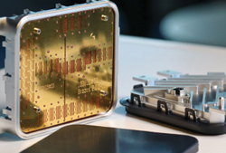
Figure 1 Automotive imaging radar antenna with housing.
Despite the technical challenges, the microwave industry has constantly reached out to higher frequencies. On the one hand, motivations are connected to necessities, such as the congestion of the already exploited spectrum, as well as to advantages, such as larger bandwidth and smaller form factors. On the other hand, the obstacles have always been the lower performance of the circuitry and less favorable propagating conditions. Recently, modern telecommunication and radar systems have moved well into the mmWave frequency bands. While this fits within this larger trend and evolution, it is a significant leap that presents considerable challenges. As a result, the technology is pushing an evolution to several established solutions in the industry, from signal processing to hardware.
When it comes to RF distribution and radiation, planar solutions based on PCB technology have often been the preferred choice, offering adequate performance for most applications at low cost with simple integration. This has also been the case for automotive radar in previous lower frequency bands and the first generations of the new 77 GHz band. However, at mmWave frequencies, issues such as low bandwidth, high losses and expensive RF substrates become significant and the perceived PCB limitations create opportunities for other technologies. Some of the alternative candidate technologies include traditional waveguides, substrate integrated waveguides (SIW), low temperature co-fired ceramics (LTCC) and lens antennas.
AUTOMOTIVE RADAR APPLICATIONS
Automotive radars have completed the migration to the 76 to 81 GHz band, now also mandated by international regulatory bodies.1 The main benefits are more accurate distance measurement due to the wider band and the easier integration of sensors on the car due to size reduction. Meanwhile, the increasing functionalities of advanced driver assistance systems (ADAS) and the rise of autonomous driving (AD) demand more capable and accurate sensors. Together with the other onboard sensors, such as cameras and lidars, radars are expected to continue having a significant role thanks to their low-cost and all-weather operation. However, to do so, radars must keep improving their performance while continuing to meet strict cost, size, thermal and reliability requirements.
To reach an accurate and complete perception of the vehicle’s surroundings, multiple radar sensor types exist.2 In ADAS applications, one often distinguishes between short-, mid- and long-range radars, based on the distance and field of view (FoV) needed for the corresponding functions, such as blind spot detection, lane change assist and forward collision warning, respectively. These sensors are specialized and increasingly ubiquitous, with massive volumes captured by a few large TIER-1 suppliers. They typically have between eight to 16 channels in a compact form factor and cost is a key factor (see Figure 2). The main performance challenge here is reaching the desired range and FoV. On the opposite end of the spectrum are the more powerful and flexible high-resolution sensors, used for example in AD systems. They are also referred to as imaging radars (see Figure 1) due to their ability to provide camera/lidar-like perception through high resolution. These more advanced and premium sensors, with 30 to 100 channels, target a young market with multiple players and smaller volumes. The main performance challenges are to realize low loss routing and complex large antennas with a massive number of channels. Clearly, the wide range of sensor types means a correspondingly broad range of priorities and optimal solutions that shall be addressed.
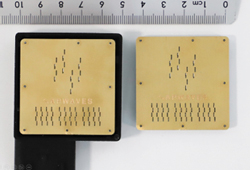
Figure 2 Compact and low cost corner radar antennas for ADAS.
GAPWAVEGUIDE TECHNOLOGY
Traditional waveguides are one of the earliest and best performing RF technologies, but bulkiness and high cost have limited them to niche high-end applications, such as satellite and military. With the miniaturization at mmWave frequency bands, only cost remains as a major obstacle even more so since tolerances become increasingly stringent. In fact, one of the most challenging and costly manufacturing aspects is ensuring an accurate fit between parts. For this reason, high precision aluminum milling and many screws are typically used. More scalable solutions exist, such as dip brazing, soldering and 3D printing, however they remain expensive and technically demanding, so not suitable for mass production.
Meanwhile, gapwaveguide technology has risen as a solution to reach the same performance in a robust and cost-effective way.3 In the most typical implementation, an equivalent transmission line can be obtained simply by replacing the waveguide side walls with an artificial magnetic conductor (AMC) texture, typically in the form of periodic posts of appropriate dimensions. Then, even in the presence of mating defects in the manufacturing or assembly of the parts, the fields remain well confined in the waveguide channel, unlike traditional hollow waveguides which instead suffer a field breakdown, as shown in Figure 3. In theory, gapwaveguide technology works for gaps up to a quarter of wavelength, 0.9 mm (about 0.04 in) at E-Band, but it is used to relax tolerances and thus lower the cost.
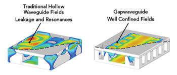
Figure 3 With small assembly defects, the fields in a standard waveguide can break down (left) while a gapwaveguide operates as designed (right).
GAPWAVES AUTOMOTIVE SOLUTIONS
Back in 2018, amid initial skepticism in the industry on waveguide solutions, Gapwaves released an automotive reference antenna,4 shown in Figure 4. Rather than an actual product, the purpose was to allow customers’ engineering teams a quick firsthand evaluation of some key capabilities through standard WR12 interfaces. From a form factor point of view, the design sported a minimalistic 1.5 layers (one core layer and a flat 2D metal one), sub 2 mm (about 0.08 in.) thickness and assembly by non-conductive glue. Performance-wise, the six channels supported the full 76 to 81 GHz band, half-wavelength spacing, narrow elevation coverage and wide and moderate in azimuth plane, using a series slotted waveguide end-fed design and optional grouping. Interestingly, despite being such an early demonstrator, several of these aspects have not yet been matched by competing technologies.
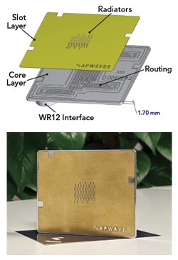
Figure 4 Gapwaves automotive reference antenna fabricated and assembled (bottom); exploded view (top).
Today, Gapwaves offers a range of technical and manufacturing solutions to best address nimble mass-volume corner sensors as well as large premium imaging radars. One of the advantages of this technology is the flexibility in manufacturing and functionality. While each application has diverse needs, the main benefits are typically linked to RF performance improvement, sensor size reduction and advanced functionalities such as thermal handling and EMC shielding.
RADAR PERFORMANCE
The main RF performance benefits are three-fold: powerful pattern control, wideband operation and high efficiency. Waveguide antennas can achieve remarkably well both very wide and focused patterns, as well as shaped ones. Vertically aligned resonant series-fed slotted waveguide antennas are an ideal building block due to their flexibility, simplicity and low profile.5 They have naturally very wide and stable radiation patterns in the horizontal E-plane (as shown in Figure 5a), beyond that of patch antennas, and enable easy control in elevation by their length and number of slots. This is ideal for short-range radars where a large azimuth FoV is critical and spacing down to half-lambda is often needed. For applications that require focusing on the azimuth plane, such as for maximum range in long-range radars, columns grouping or hard surfaces are used. Shaped beams, such as in corner radar where the direction of the maximum range is at about 40 degrees, can be obtained by careful phase and amplitude control.
When it comes to operational bandwidth, unlike PCB patch solutions, waveguides can easily support the full 76 to 81 GHz automotive band. This gives flexibility in frequency allocation and more accurate distance measurement. For this purpose, both impedance and, more importantly, radiation patterns must be well-behaved, which is more challenging the narrower the beamwidth. Figure 5b shows the pattern response across the full band of a long antenna with a beamwidth of 10 degrees.
High efficiency is the most well-known advantage of the technology. At the antenna level, losses are the most negligible even for high gain elements. When it comes to routing, typical losses at E-Band are around 0.01 to 0.02 dB/mm (0.25 to 0.5 dB/in.) depending on the design and material characteristics, about an order of magnitude lower than typical microstrip solutions. This is particularly beneficial for large and multi-layer sensors such as imaging radars, as shown in Figure 6, where the antenna size and layout may require tens of centimeters long routing lines, including crossovers. Of course, designing and manufacturing large sensors with several channels is a challenge.
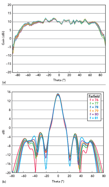
Figure 5 Wide and consistent azimuth radiation patterns of eight samples (a) and narrow elevation patterns across 76-81 GHz (b).
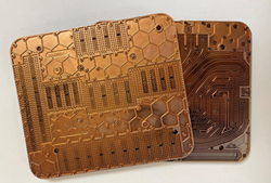
Figure 6 Imaging radar antenna showing long and complex routing.
INTEGRATION
Waveguide antennas enable sensor size reduction with respect to PCB counterparts. The antenna is located above the PCB with a clearance to host components underneath. This frees the area otherwise occupied by the antennas and removes any component influence on the radiation characteristics. However, a simple, robust and high performance integration is a key aspect since the entirety of the electronics live on the PCB and within the sensor assembly. Consequently, a portfolio of readily available transitions for a wide range of feeding configurations and substrates, from high- to low-end ones have been designed. Most typical solutions have simple via-less PCB designs and losses in the lower part of a dB, as shown in Figure 7a. Alternatively, drop-in launcher-in-package interfaces are available for the main chip manufacturers, as shown in Figure 7b. These unique chips inject the signal directly into the antenna with integrated launchers, entirely bypassing the PCB.6 This further reduces the losses and completely removes the need for the RF substrate. In all of these cases, gapwaveguide technology is used to allow a robust interface where no electrical contact is needed between the antenna and the PCB and hundreds of microns in tolerances in all directions are supported.
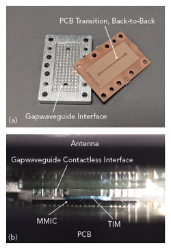
Figure 7 Gapwaves antenna interface to a PCB (a) and direct launch-in-package (b).
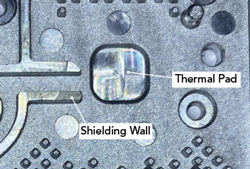
Figure 8 Using metallic layers improves the thermal and EMC performance of the radar sensor.
Moreover, waveguide integration can provide additional functionalities. Often RF systems are thermally limited, due to the low power efficiency of high frequency electronics, compact dimensions and typical high temperature environments. Thus, the thermal design aspects are often critical and challenging to overcome. In those cases, the antenna body can offer an additional heat dissipation path by using thermally conductive materials in direct contact with the electronics. Another challenging aspect in sensors is electromagnetic compatibility (EMC), where the device must not infringe regulations on radiated out-of-band emissions. Again, an antenna made of electrically conductive material can suppress the emission by closely surrounding the critical part of the circuitry and shielding them. Figure 8 shows a die cast metal antenna layer that serves both of these functions in addition to the electrical ones: the protruding square area at the center is offering a thermal connection to the active component while the surrounding walls improve the EMC shielding.
MANUFACTURING AND SUPPLY
Gapwaves has developed a variety of manufacturing processes. Low volume prototyping is mostly handled by metal or plastic CNC machining, due to its speed and accuracy. This has proved to be a sensible first verification and a reliable benchmark for the actual parts which have greater lead times and deviations. For high volume production, Gapwaves currently employs three main processes: plastic injection molding, metal die casting and sheet metal stamping.
Plastic injection molding produces complex, lightweight parts and is often the first choice for automotive applications. Non-conductive plastic parts are then coated with a thin metal layer, typically copper by physical vapor deposition for the best performance to cost ratio. Alternatively, die casting can be used to produce bulk aluminum or zinc parts. This solution offers superior thermal and EMC handling and greater flexibility on some geometries. Finally, sheet metal manufacturing produces accurate thin 2D parts. Unlike other processes, this is cost-effective both at low and high volume by choosing between laser cutting, chemical etching or stamping. For this reason, it is often preferred for simple parts since it lowers the cost with respect to a fully 3D product. Given the differences between each process, it is important to choose the best one according to the application. Moreover, it is quite common to combine them, for example, metal casting close to the electronics, molding for other 3D parts and sheet metal for simple layers such as the radiating one, as shown in Figure 9.
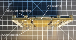
Figure 9 Antenna fabricated using multiple volume manufacturing processes.
When it comes to the supply chain, Gapwaves has partnered globally to manufacture its parts in the most flexible and cost-effective way. For low to mid volumes, antennas can be delivered directly from Gapwaves facilities, while for large volumes, partners are extensively used. Gapwaves’s philosophy is to team up with large and established suppliers for volume scaling and expertise in cost-effective manufacturing. The company leverages its expertise in manufacturability by assisting partners in getting the critical dimensions correct for proper performance. The company has also developed the required equipment for the non-readily available processes needed to transform loose parts into a complete antenna, such as assembly and test.
RELIABILITY AND TESTING
As with any technology in a new market, building a reputation of maturity is crucial. For this reason, extensive testing and qualification are desired for ensuring defect-free manufacturing and reliable field operation. Interestingly, unlike PCB-based antennas, waveguides enable easy and direct testing with their accessible interface. Measuring early at the antenna level has the advantage of unambiguously tacking its performance and catching faulty units without scrapping the entire assembled sensors. Seeing this upcoming need and opportunity, Gapwaves has developed an inline test system for the production lines as shown in Figure 10. The system is fast and flexible, measuring any type of antenna in a few seconds.

Figure 10 Gapwaves rapid inline antenna test system.
Reliability is an aspect of paramount importance. The automotive industry typically requires demanding environmental standards, including harsh temperature, humidity, shock and vibration tests. These products have been fully qualified to automotive standards, such as IEC60068-2, and perform tailored qualifications at the customer’s request. The ruggedness of a product is the result of several design and manufacturing aspects and is challenging to master. Over the years the company has developed strong expertise to support customers and supply partners.
CONCLUSION
Gapwaves’ unique waveguide technology offers automotive radars unprecedented performance capabilities. Thanks to the robustness and relaxed manufacturing tolerance, advanced antennas are now a reality for low-cost, mass-volume markets. Some of the key benefits are powerful pattern control, full band support, minimal losses as well as sensor size reduction, thermal dissipation and EMC shielding. Moreover, leveraging the technology’s flexibility, a wide range of building practices and manufacturing processes are available for every application and volume. From nimble mass-volume to complex premium sensors, gapwaveguide technology offers superior tailored solutions. These benefits enable any radar sensor to improve performance and help sensor manufacturers to meet the demands required by modern driver assist and autonomous systems.
Read more
Microwave Journal
Gapwaves, radar antennas
References
- “Permitting Radar Services in the 76-81 GHz Band,” Federal Communications Commission, 82 FR 43865, pp. 43865-43872, September 2017, Web: https://www.govinfo.gov/content/pkg/FR-2017-09-20/pdf/2017-18463.pdf.
- J. Hasch, E. Topak, R. Schnabel, T. Zwick, R. Weigel and C. Waldschmidt, “Millimeter-Wave Technology for Automotive Radar Sensors in the 77 GHz Frequency Band” IEEE Transactions on Microwave Theory and Techniques, Vol. 60, No. 3, March 2012.
- P. S. Kildal, E. Alfonso, A. Valero-Nogueira and E. Rajo-Iglesias, “Local Metamaterial-Based Waveguides in Gaps Between Parallel Metal Plates” IEEE Antennas and Wireless Propagation Letters, Vol. 8, 2009.
- “Gapwaves Releases 77 GHz Waveguide Antenna for Automotive Radar,” Web: https://gapwaves.com/pressreleases/gapwaves-releases-77-ghz-waveguide-antenna-for-automotive-radar/,http://gapwaves.com/wp-content/uploads/2022/10/Automotive-reference-antenna-1-1.pdf.
- A. Haddadi, C. Bencivenni and T. Emanuelsson, “Gap Waveguide Slot Array Antenna for Automotive Applications at E-Band,” 2019 13th European Conference on Antennas and Propagation (EuCAP), 2019, pp. 1–4.
- Q. Ren, C. Bencivenni, A. Uz Zaman, J. Yang, G. Carluccio and H. T. Shivamurthy “Millimeter-wave Gap-waveguide Interconnect for Launcher in Package Technology,”16th European Conference on Antennas and Propagation (EuCAP), 2022.